


On most variants of the Ford Galaxy, Mondeo and S-Max produced in the period 2006-2015 and the Volvo S / V / XC 60 and V / XC 70 produced in the period 2007-2014, the replacement of the track control arm bushing is an inconvenient and time-consuming work process.
AST has changed this with a super smart installation set - AST5114 - which enables replacement of the bushing without necessarily having to completely disassemble the support arm.

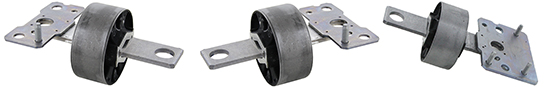
AST5114
1. Press tool frame
2. Pressure cylinder
3. Insert for removing the bushing
4. Insert for mounting the bushing
5. Locking ring
Triscan ref. 8500 16839 (OE: ex. 1566810), 8500 16840 (OE: ex. 1566837) og 8500 27833 (OE: ex. 31387282)
Procedure for removing the bushing
Regarding the use of the press tool frame, it is important to underline the following.
ALWAYS make sure that the tool spindle is lubricated with oil. NEVER use air or electric impact wrenches.
1. Remove the bottom bolt of the shock absorber and the support link bar bolt from the track control arm.
2. Unclip the cables and the electrical wiring and detach the bracket.
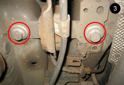
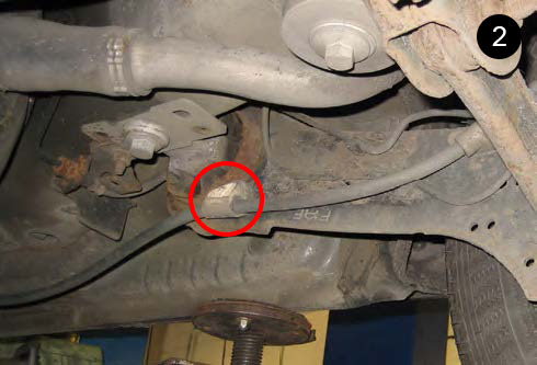
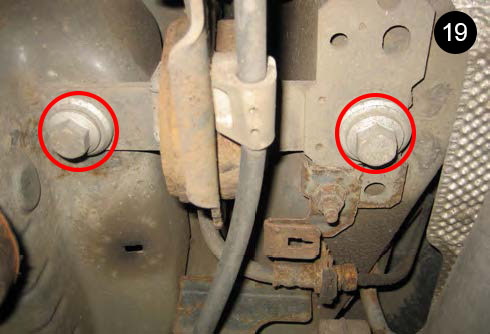
3. Remove the 2 bolts that secure the front end of the track control arm to the underside of the vehicle.
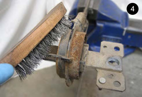
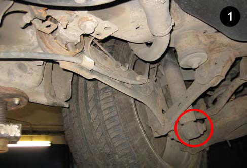
4. Pull the front of the track control arm down, away from the underside of the vehicle, giving access to the bushing. Using a suitable method such as a wire brush, remove any loose pieces of corroded metal from the outer sleeve of the bushing.

5. Before removing the track control arm bushing, take note of the position of the bushing, including the distance that the outer sleeve of the bushing protrudes from the outside of the track control arm.
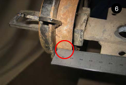
6. NOTE: During the installation of the new bushing, the correct position can be ensured by means of a rubber-molded pin, which must be positioned next to a cut-out in the edge of the track control arm. If the track control arm does not have this cut-out, the position must be marked before the old bushing is removed to ensure that the correct bushing position is achieved.

7. Fit the removal adaptor plate over the 'T' shaped end of the bushing and place it flat against the track control arm so that the cable mounting bracket is located in the recess of the insert.
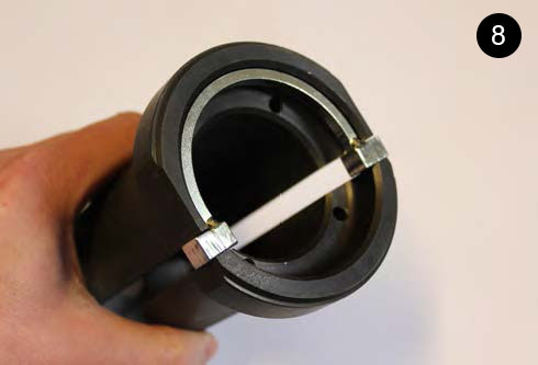
8. Insert the distance ring into the pressure cylinder.
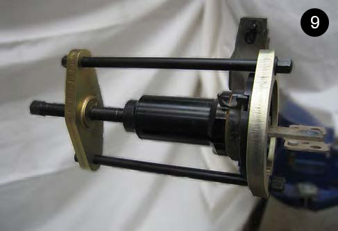
9. Fit the press tool frame and the pressure cylinder over the bushing and the track control arm. Then place it so that the pin on the base plate of the frame is located in the slot on the insert for removing the bushing.

10. Without the use of tools and only with the hand, the power screw is now tightened just so hard that the frame is only held in position.
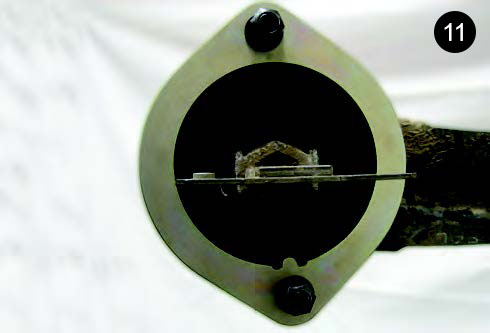
11. Before pressing the bushing from the track control arm, check that the tool is correctly positioned. If the position is not correct, it can lead to the squeezing of the bushing causing damage to the tool and the track control arm.
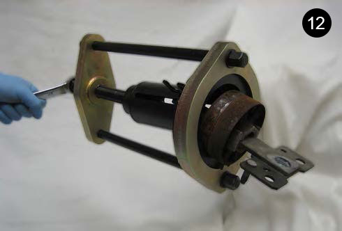
12. Once you have made sure that the bushing and the bushing tool are properly adjusted, use a 24 mm wrench to tighten the bushing tool power screw. You can now slowly and evenly push the bushing out of the track control arm.

Procedure for mounting the bushing
Make sure that the indentation hole for the bushing in the track control arm is clean and free of dirt/corrosion.

13. Place the insert for mounting the bushing into the press tool frame. Make sure that the insert is positioned correctly (the pin of the press tool frame is fully located in the slot of the insert).

14. Place the press tool frame with insert on the track control arm with the cable mounting bracket located in the opening on the insert. This ensures that the press tool frame is positioned correctly in relation to the mounting of the bushing.
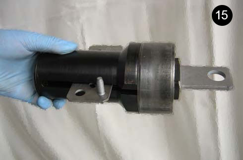
15. Make sure that the distance ring is inserted in the pressure cylinder. Place the new bushing in the slot on the pressure cylinder. Hereby the outer ring of the bushing and the end face of the pressure cylinder are placed correctly in relation to each other.

16. Place the pressure cylinder with the inserted bushing in the press tool frame. Without the use of tools and simply with the hand, the power screw is now tightened just so hard that the frame is only held in position.

17. Check that the bushing, track control arm and press tool frame are correctly positioned. The rubber pin moulded into the bushing should align with the cut-out/alternatively your own marking on the track control arm. The power screw, the pressure cylinder and the bushing position must all be adjusted correctly to ensure that the bushing is pressed correctly into the track control arm.

18. When the bush and bush tool are correctly aligned to the trailing arm, use a 24mm spanner to tighten the Force Screw of the Bush Tool, slowly and smoothly pressing the bush into the trailing arm. Continue until the outer sleeve of the bush is positioned correctly within the arm. Monitor the movement of the bush, ensuring that it remains square as it enters the trailing arm.
19. Remove the bushing tool from the track control arm. Lift the track control arm into place and mount the 2 fastening bolts that secure the track control arm to the underside of the vehicle. Mount the bracket to the track control arm bushing. Reattach the shock absorber, cables and wires.